
Best Ball End Mills for CNC Machining in 2026
Choosing the best ball end mills for CNC machining in 2026 starts with the surface, not the catalog. A Ball End End Mill leaves curved passes that can feel smooth under a fingertip or show tiny ridges under angled light. Tool diameter, corner geometry, flute count, coating, and workpiece material all affect the result. So does the machine. A sharp cutter cannot compensate for a loose holder or poor setup.
Dr. David Stephenson is a recognized machining researcher and author. A practical paraphrase of principles in his machining work is: “Reliable cutting begins with understanding the tool, the material, and the conditions at the cut.” This is a paraphrase, not a verified verbatim quotation. It captures a useful rule for comparing tools: match the cutter to the job, then test the setup.
This guide considers finishing quality, tool life, rigidity, and chip evacuation across common CNC applications. It also looks at step-over, because a small change can alter both surface texture and machining time. For hardened steel, aluminum, and mold work, the ideal choice may differ. There is no perfect cutter. Even a promising tool can disappoint when runout, stickout, or feed settings are overlooked. The comparisons ahead offer practical selection criteria, while leaving room for careful test cuts and shop-specific judgment.
What Ball End Mills Are and How They Cut
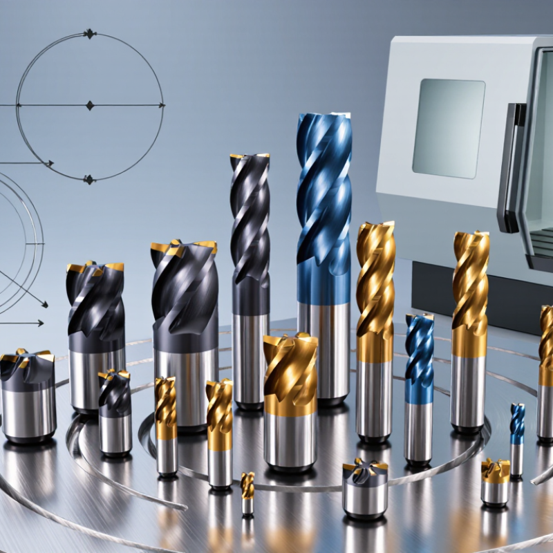
A ball end mill has a rounded tip, shaped like half a sphere, rather than a flat cutting end. Its flutes cut as the tool follows a programmed path across the workpiece. This makes it useful for sculpted surfaces, curved pockets, and rounded transitions. Not just flat floors. The tool leaves a scalloped pattern, so the programmed stepover affects how visible those marks are. Smaller stepovers usually reduce scallop height, but they also increase machining time.
Cutting conditions change near the tool’s center. There, the effective cutting speed approaches zero, which can encourage rubbing instead of clean shearing. A sound toolpath keeps the cutting edges engaged where possible and avoids lingering at the tip. For a contoured mold, for example, a machinist may combine roughing passes with a finer finishing path.
The ball shape is useful, but not magic. It may leave poor results if the tool deflects, chips cannot clear, or the chosen stepovers are too wide. Checking the material, flute length, toolpath, and surface marks helps explain what needs adjustment. There is always a trade-off between finish, cycle time, and tool life.
Key Designs, Materials, and Coatings in 2026
Ball end mill performance in 2026 depends on matching geometry to the cut, not simply choosing the hardest tool. A polished, constant-radius tip helps produce clean contours, while a variable helix can reduce chatter on slender walls. Small details matter. Neck relief also deserves attention: too little clearance may cause rubbing inside a deep cavity, even when the cutting edges remain sharp.
Fine-grain carbide is a practical choice for many CNC finishing and semi-finishing jobs. Its stiffness helps limit deflection, but a long tool can still flex under load. Use the shortest reach that clears the part. For aluminum, a sharp edge and smooth flute surface help manage built-up material. In harder steels, a wear-resistant coating such as AlTiN may tolerate elevated cutting temperatures; coating choice should still match the workpiece and coolant strategy.
Flute count affects chip space and surface finish. Two or three flutes often leave room for chips in softer materials, while more flutes can support finer finishing in suitable conditions. Not always. A coating cannot fix poor chip evacuation or an incorrect feed rate. Check the toolmaker’s speed and feed data, then adjust cautiously using spindle load, sound, and the machined surface as evidence. Slightly conservative settings may be sensible, though they can also waste cycle time.
| Design or Configuration | Typical Material | Common Coating or Surface | Suitable Work and Use | Selection Considerations |
|---|---|---|---|---|
| Two-flute, polished ball end mill | Solid carbide | Uncoated, polished flutes | Aluminum and other nonferrous materials; finishing where chip space and a clean surface are priorities | Polished, sharp flutes can help limit built-up edge. Use appropriate chip evacuation and avoid rubbing, especially in small tools. |
| Three-flute ball end mill | Solid carbide | Uncoated or application-specific coating | General-purpose profiling and finishing in nonferrous materials and some steels | A middle ground between flute space and cutting-edge count; check the tool maker’s recommended feed, speed, and engagement for the material. |
| Four-flute ball end mill | Solid carbide | AlTiN or TiAlN for suitable ferrous applications; uncoated options also available | Finishing and profiling in steels and other materials when the chip load and setup suit the flute count | More flutes can provide additional cutting edges but less room for chips. Ensure the chosen flute count is appropriate for the material and operation. |
| Variable-helix or variable-pitch ball end mill | Solid carbide | Often a wear-resistant coating selected for the work material | Contoured milling where reducing vibration or chatter is important | Unequal spacing can disrupt harmonic vibration, but it does not replace a rigid setup, sound toolholding, or suitable cutting parameters. |
| Long-reach or necked ball end mill | Solid carbide | Coating chosen for the workpiece material; uncoated versions are also used | Deep cavities, steep walls, and features with limited access | Neck relief provides clearance, while the extended reach increases deflection risk. Use the shortest reach that can access the feature and keep engagement controlled. |
| High-hardness finishing ball end mill | Fine-grain solid carbide | AlTiN or TiAlN, where compatible with the material and cutting conditions | Finishing hardened steels and other difficult-to-machine ferrous materials within the tool’s specified hardness range | Confirm the tool’s rated workpiece hardness and operating limits. Coating choice, heat management, and stable machine setup are important. |
| Nonferrous-material ball end mill | Solid carbide | Polished and uncoated, or a coating specifically intended for nonferrous materials | Aluminum, copper alloys, and other nonferrous workpieces, depending on tool geometry | Some hard coatings can be unsuitable for aluminum if they encourage material adhesion. Check coating compatibility and prioritize sharp edges and chip clearance. |
| High-speed-steel ball end mill | High-speed steel (HSS) | Uncoated or a coating specified for the tool and application | Lower-speed machining, less-rigid setups, or applications where a more compliant tool material is preferred | HSS generally has lower hot hardness and wear resistance than carbide, so cutting speeds and expected tool life differ. Follow the tool supplier’s limits. |
Selection note: The appropriate ball end mill depends on workpiece material, hardness, feature geometry, tool reach, machine rigidity, toolholding, and finishing requirements. Coating names indicate coating families, not a universal performance ranking; verify compatibility and cutting data with the tool supplier.
How to Match a Ball End Mill to Your CNC Application
Best Ball End Mills for CNC Machining in 2026
Matching a ball end mill to a CNC job starts with the surface shape, not the tool catalog. For tight 3D curves or small internal radii, a smaller ball can reach the detail. It also has a weaker tip, so reduce tool stickout and watch for chatter. A larger radius can cover more area per pass and leave a smoother scallop at the same stepover. That is not always the best choice near narrow features.
Consider the workpiece and machine setup together. Carbide tools suit many demanding CNC operations, but the right flute count depends on chip space, material, and cut conditions. Aluminum often needs clear chip evacuation; harder alloys may call for a tougher edge and more conservative engagement. Check the recommended cutting data for the tool and material, then adjust based on spindle power, coolant, and actual chip formation. Small test cuts help. They can also reveal a poor assumption before it becomes a costly finish pass.
Tips: Keep the tool as short as the geometry allows. Use a stepover suited to the finish requirement, and inspect the surface under consistent lighting. A faint ridge may be easy to miss at the machine. If vibration appears, reduce engagement or improve workholding before simply slowing the feed. There is no universal setting; even a sound tool choice can disappoint when the holder, reach, or setup is overlooked.
Comparing Ball End Mills by Performance and Tool Life
Best Ball End Mills for CNC Machining in 2026
Comparing ball end mills means looking beyond cutting speed. Substrate, flute shape, coating, and tool runout all affect surface finish and wear. A fine-grain carbide tool can resist edge chipping, while a suitable coating may reduce heat when cutting harder materials. Neither feature guarantees longer tool life. The workpiece, setup, and cutting conditions still matter.
For three-dimensional contours, a polished flute can help chips clear the cutting zone, especially in aluminum. In steel, a stronger edge may be more useful than an aggressive geometry. A two-flute design often leaves more room for chip evacuation; additional flutes can improve finish when the machine maintains a stable cut. Watch for a dull sheen or small ridges on the machined surface. These can signal wear, but runout or loose workholding may cause similar marks. Small details matter.
A fair tool-life comparison uses the same material, toolpath, coolant, and finish target. Record cutting time and inspect the ball nose under magnification, rather than judging wear by sound alone. Reduce stepover gradually if scallops remain, but remember that a smaller stepover adds machining time. That trade-off is easy to underestimate. Even careful tests have limits: one machine’s results may not transfer cleanly to another. Check the actual cut before extending tool life based on a catalog estimate.
Setup, Feed Rates, and Maintenance for Reliable Machining
Best Ball End Mills for CNC Machining in 2026
Reliable ball-end milling starts with a rigid setup. Keep tool projection short, clean the holder taper, and check runout near the cutting edge; even small wobble can leave visible ridges on a curved surface. Ball tools cut slowly near their center, where effective cutting speed approaches zero. Tilt the tool or use a suitable stepover to keep the contact point away from the tip when the machine and geometry allow. Check the machine’s limits, too.
Set feed from the actual flute count and chip load, not a generic chart alone. Machinery’s Handbook, 31st edition, gives the standard relationship: feed rate equals spindle speed multiplied by flutes and feed per tooth. For example, 10,000 rpm, two flutes, and 0.03 mm per tooth gives 600 mm/min. Treat that as a calculation example, not a universal setting. Material, engagement, stickout, and coolant can change the safe starting point. My own setup notes are not always complete; that makes repeat tests worth the extra minutes.
Tips: Start with a conservative cut, then adjust one variable at a time. Listen for chatter. Inspect the ball nose for edge wear and built-up material after finishing passes. ISO 8688-2:1989 describes controlled tool-life testing in milling; consistent inspection criteria make wear comparisons more useful than memory alone. Keep a simple log of tool hours, finish quality, and the settings that produced both.
Ball End Mill CNC Feed Rates: 2026 Starting Estimates
Illustrative starting estimates for a 6 mm, two-flute ball end mill, calculated as feed rate = spindle speed × flutes × chip load. The examples assume the full 6 mm diameter is engaged: aluminum (150 m/min surface speed, 0.050 mm/tooth), mild steel (90 m/min, 0.030 mm/tooth), stainless steel (60 m/min, 0.020 mm/tooth), and titanium (45 m/min, 0.015 mm/tooth). Actual settings depend on tool geometry, machine rigidity, material condition, and engagement. For ball-end cutting, use the effective cutting diameter at the engagement height when calculating spindle speed, and verify settings with a cautious test cut.
English
Français 