How to Choose the Right BMS PCB for Your Product?
Choosing the right Battery Management System PCB (BMS PCB) can determine whether a battery product performs reliably in real operating conditions. The board must monitor cell voltage, temperature, current, and charging status with consistent accuracy. A small measurement error can reduce usable capacity or create an unsafe charging decision. Designers should examine the battery chemistry, cell count, peak current, communication interface, and expected operating temperature before selecting a circuit.
A compact lithium-ion pack may need a six-cell BMS PCB with balancing control, several thermistor inputs, and CAN communication. A high-current industrial module may require wider copper paths, stronger MOSFETs, isolated communications, and improved heat dissipation. Look closely at the shunt resistor, connector ratings, creepage distances, and protection thresholds. These details often matter more than a long feature list. They also affect enclosure size, wiring complexity, production cost, and service access.
A reliable selection process combines manufacturer documentation, test data, and application-specific validation. Check whether the design supports relevant safety and performance expectations, such as IEC 62133 or UL 1973, where applicable. Certification alone is not a complete guarantee. A certified board can still be poorly matched to your cells, charger, or firmware strategy. That is an easy mistake to make. Engineers should test abnormal temperatures, sudden load changes, communication loss, and repeated charge cycles. In practical design reviews, teams sometimes focus on maximum current and overlook balancing speed. That oversight can appear only after months of field use. The best choice balances protection, measurement accuracy, integration effort, maintainability, and realistic production requirements. It may not be the cheapest option, but it should be explainable, testable, and dependable.
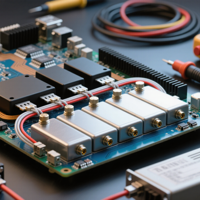
Define the Role of a BMS PCB in Your Product
A BMS PCB is the product’s electrical control center. It measures cell voltage, pack current, and temperature. It also controls balancing, charging, discharge, communication, and emergency shutdown. The PCB connects battery cells with the charger, motor, or device load. Its role depends on the product, not only the battery size. The International Energy Agency reported that electric vehicle battery demand exceeded 750 GWh in 2023. This growth increases pressure on accurate sensing and reliable protection.
When choosing a BMS PCB, define the battery architecture first. Record the cell chemistry, series count, peak current, operating temperature, and expected service life. A compact medical device may need low noise and careful temperature monitoring. An industrial pack may require stronger switching components and communication diagnostics. Designers sometimes choose a higher current rating and stop there. That can be misleading. Thermal paths, connector limits, balancing speed, and software response also shape real performance. I have seen prototypes pass basic tests but fail during repeated high-load cycles. The PCB must match the complete operating profile.
Tips: Leave measurement margins for voltage and temperature. Check balancing performance at low charge levels. Review creepage, clearance, EMC, and fault-handling requirements early. Ask for test evidence, not only a specification sheet. A useful design review includes abnormal conditions, because normal operation rarely reveals every weakness. Reconsider the choice after thermal testing.
Assess Battery Chemistry, Voltage, Capacity, and Cell Configuration
How to Choose the Right BMS PCB for Your Product?
Battery chemistry determines the BMS PCB’s voltage limits, balancing method, and safety thresholds. Lithium-ion NMC cells usually charge to 4.2 volts, while LFP cells typically charge near 3.65 volts. Choosing the wrong setting can cause early aging or unsafe overvoltage. The International Energy Agency reported that LFP chemistry represented nearly 40% of the global electric vehicle battery market in 2023. Chemistry changes everything. Confirm the cell manufacturer’s specifications, not only the common chemistry label.
Next, calculate voltage from the series count. A 13S NMC pack reaches about 54.6 volts when fully charged, while a 16S LFP pack reaches about 58.4 volts. The PCB must support this maximum voltage, plus suitable measurement accuracy.
Capacity comes mainly from parallel cells, but the BMS must also handle continuous and peak current. The IEA’s Global EV Outlook 2024 estimated that electric vehicle battery demand exceeded 750 GWh in 2023, showing how quickly large battery systems are scaling. Bigger capacity does not automatically mean safer operation.
Cell configuration deserves a physical inspection. Check connector order, temperature-sensor placement, balancing current, and protection response time. Real cells age unevenly. A spreadsheet can still lie. Measure actual discharge current, temperature rise, and resting voltage during prototype testing. The Battery Technology Roadmap from the U.S. Department of Energy highlights the importance of thermal management, durability, and reliable battery monitoring across changing operating conditions. Leave engineering margin; a PCB rated exactly at the calculated limit may fail when cells warm, cool, or drift apart.
Match BMS Protection Functions to Product Safety Requirements
How to Choose the Right BMS PCB for Your Product?
A BMS PCB should reflect the product’s real safety risks, not only its battery voltage. The IEA Global EV Outlook 2024 reported that battery demand from the energy sector reached about 750 GWh in 2023, rising approximately 40% in one year. This growth increases pressure on designers to verify protection functions carefully. For a compact consumer device, overvoltage, undervoltage, overcurrent, short-circuit, and temperature monitoring may be essential. A larger energy-storage system may also require cell balancing, contactor control, insulation monitoring, event logging, and communication redundancy.
Map each function to a measurable hazard. If a cell may overheat during charging, the PCB needs accurate temperature sensing and a tested charging cutoff. If the product operates near vibration or moisture, connector reliability and fault detection deserve equal attention. IEC 62133-2 and UL 1973 provide useful safety frameworks, while ISO 26262 supports more structured risk analysis for vehicle applications. Requirements differ.
Do not choose a PCB from nominal voltage alone. That shortcut is tempting. Review peak current, charging speed, cell chemistry, operating temperature, fault response time, and required service life. The 2024 Battery Safety Report from the U.S. Department of Energy emphasizes detection, prevention, and mitigation as connected safety layers. In practice, I would test abnormal charging, blocked cooling paths, sensor disconnection, and communication loss. One weakness remains easy to miss: a BMS can report safe values while a poorly placed sensor reads the wrong temperature. Functional coverage must be tested inside the finished enclosure.
Evaluate Communication, Size, Thermal Design, and Integration Needs
How to Choose the Right BMS PCB for Your Product?
Evaluate Communication, Size, Thermal Design, and Integration Needs
Selecting a BMS PCB starts with the product’s real operating conditions. Communication needs should match the host controller and service process. CAN suits robust vehicle networks, while UART may simplify compact equipment. Confirm protocol settings, message formats, fault reporting, and update methods before ordering samples. Check electrical isolation when cables leave the enclosure. A prototype test with an oscilloscope can reveal noise that specifications miss. Small details matter.
Size is more than board length and width. Review connector positions, mounting holes, cell-tap spacing, and clearance around high-current paths. Thermal design deserves equal attention. Measure heat near power switches, balancing resistors, and current sensors during continuous operation. Use airflow and enclosure tests, not only room-temperature bench tests. A board that fits perfectly may still trap heat. That mistake is easy to make.
Integration also includes firmware behavior and production testing. Confirm voltage, current, temperature, and state-of-charge accuracy with calibrated equipment. Define responses to overvoltage, short circuits, sensor failure, and communication loss. Ask whether thresholds can be configured without weakening essential protections. During one design review, we found that a convenient connector blocked service access. It worked electrically, but poorly in the field. Leave room for wiring, inspection, and future revisions. Document every assumption, including cell chemistry, charge rate, expected load, and installation environment.
Compare Compliance, Reliability, Customization, and Total Cost
How to Choose the Right BMS PCB for Your Product?
Compare Compliance, Reliability, Customization, and Total Cost
Choosing a BMS PCB requires more than checking voltage and current ratings. Compliance is not a paperwork exercise. Ask for test reports, traceable components, and production records. Relevant requirements may include IEC 62133-2, UL 1973, or UN 38.3, depending on the market and battery application. Requirements also vary with chemistry, energy capacity, and product location. A certificate alone does not prove a suitable design. Review its scope carefully.
Reliability starts with protection performance under real conditions. Examine overcharge, over-discharge, short-circuit, thermal, and communication fault responses. Sensor placement matters. A sensor near a warm MOSFET may report a misleading temperature. Request evidence from vibration, thermal cycling, and aging tests. Test it hard. A BMS that works in a quiet laboratory may behave differently inside a sealed enclosure.
Customization should support the product, not complicate it. Cell count, balancing current, connector layout, communication protocols, and firmware limits may need adjustment. Useful options include CAN, UART, Bluetooth, and data logging. However, each option adds validation work and future failure points. Total cost includes tooling, certification, firmware updates, inventory, and field service. Cheap prototypes can become expensive products. In practice, the lowest purchase price is often not the lowest ownership cost. Some teams also underestimate replacement access, which can turn a minor failure into a costly repair.
English
Français