 English
 Français

What Is a Millimeter Wave Amplifier?
What Is a Millimeter Wave Amplifier? The question sounds simple, but the answer reaches into the small, warm hardware inside a radio. A Millimeter Wave Amplifier increases the power of signals at very high frequencies, commonly used in 5G links, radar, and satellite systems. It may sit near an antenna, where a short trace or waveguide carries a fragile signal. Small details matter. A connector can add loss. A warm circuit can shift performance.
Wireless researcher Theodore S. Rappaport has studied millimeter-wave communication extensively. A fair paraphrase of a lesson from his work is: “Wide bandwidth is possible, but propagation still sets the rules.” This is not a verbatim quotation. At these frequencies, walls, rain, antenna alignment, and nearby objects can affect a link. The amplifier must provide useful gain without adding too much noise or distortion. Engineers check those trade-offs with measurements such as gain, noise figure, output power, and linearity. A spectrum analyzer may show a clean signal at one setting, then reveal unwanted distortion when the amplifier is pushed harder. That is easy to overlook.
The design is not just about making a signal louder. It is about preserving its shape, controlling heat, and fitting the amplifier into a real system. One result may look excellent on a bench and disappoint inside a compact device. That gap deserves attention. This guide explains how millimeter-wave amplifiers work, where they are used, and which specifications help readers judge them.
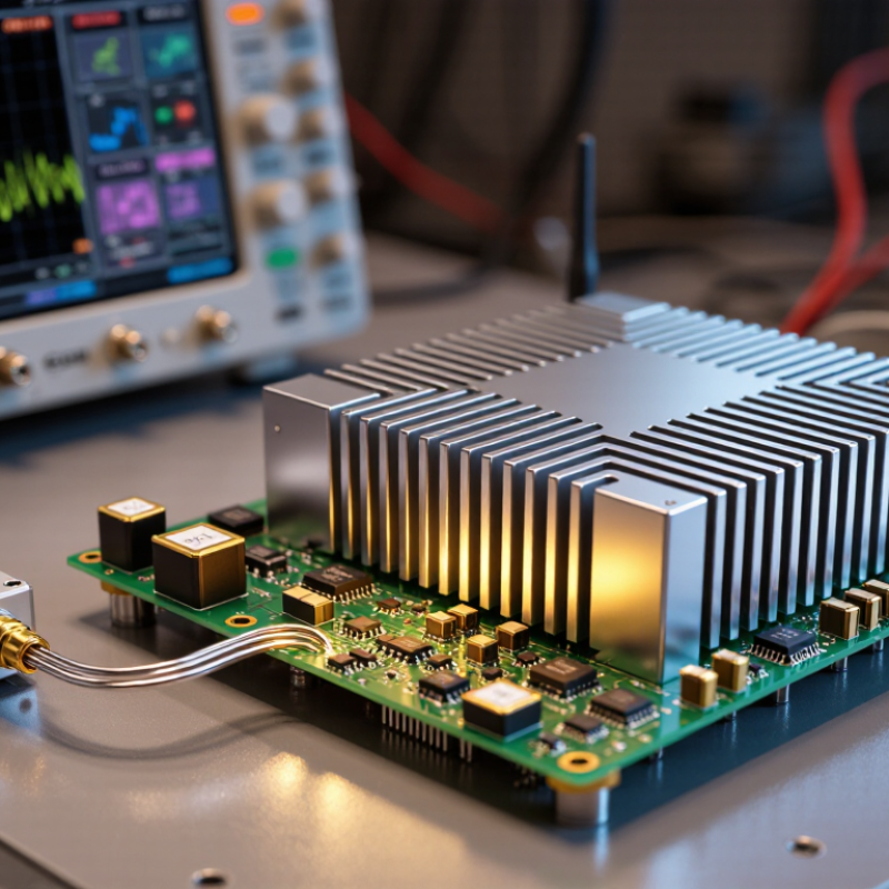
Millimeter-Wave Amplifiers: The 30–300 GHz Frequency Range
What Is a Millimeter Wave Amplifier?
Millimeter-Wave Amplifiers: The 30–300 GHz Frequency Range
Millimeter-wave amplifiers operate across roughly 30 to 300 GHz, where wavelengths shrink from about 10 millimeters to 1 millimeter. They increase weak radio-frequency signals so receivers can detect them or transmitters can deliver more output power. The range is broad. A circuit designed near 30 GHz may behave very differently from one near 300 GHz.
At these frequencies, small physical details matter. A connector, circuit trace, or poorly aligned waveguide can introduce noticeable signal loss. Engineers therefore check gain, noise, output power, and stability across the intended bandwidth, not just at one convenient test frequency. Calibration matters, too. A lab cable that looks ordinary can affect a measurement.
These amplifiers support applications such as high-capacity wireless links, radar, and scientific instruments. Each use places different demands on bandwidth, linearity, efficiency, and signal cleanliness. More gain is not automatically better; excess amplification can add noise or distort a strong signal. That sounds tidy on paper. Real benches are less tidy, and results can shift with temperature, packaging, or test setup. The 30–300 GHz label describes a frequency region, not a promise that one amplifier covers it all. Check the specified operating band and measurement conditions before comparing devices.
What Is a Millimeter Wave Amplifier? - Millimeter-Wave Amplifiers: The 30–300 GHz Frequency Range
A millimeter-wave amplifier increases the power of signals at very high microwave frequencies. The term millimeter wave commonly refers to frequencies from about 30 to 300 GHz, where free-space wavelengths are approximately 10 to 1 millimeter.
| Frequency range | Approximate wavelength | Common band names or examples | Typical uses | Amplifier design considerations |
|---|---|---|---|---|
| 30–50 GHz | 10–6 mm | Lower millimeter-wave frequencies; portions of the Ka band | Satellite communications, high-capacity point-to-point links, and scientific instrumentation | Gain, output power, and noise performance must be balanced against transmission-line and component losses. |
| 50–75 GHz | 6–4 mm | V band; 57–71 GHz is used for unlicensed-device applications in some regions | Short-range multi-gigabit wireless links, data-center links, and radar research | Atmospheric absorption is relatively strong near 60 GHz, so link distance and local regulations matter. |
| 75–110 GHz | 4–2.73 mm | W band; E-band links include 71–76 GHz and 81–86 GHz | Fixed wireless backhaul, automotive radar around 76–81 GHz, and imaging systems | Low-loss packaging, antenna integration, and thermal management become increasingly important. |
| 110–170 GHz | 2.73–1.76 mm | D band includes 110–170 GHz in common band nomenclature | Experimental high-capacity communications, spectroscopy, and passive or active imaging | Small circuit dimensions and connector or waveguide transitions require precise fabrication and calibration. |
| 170–220 GHz | 1.76–1.36 mm | Submillimeter-wave region | Laboratory spectroscopy, atmospheric research, and specialized imaging | Available output power is often limited; measurement fixtures and interconnect losses can strongly affect results. |
| 220–300 GHz | 1.36–1 mm | Upper millimeter-wave and submillimeter-wave region | Research communications, material analysis, and high-resolution sensing | Very high-frequency operation places demanding requirements on device technology, packaging, and measurement equipment. |
| Amplifier gain | Reported in decibels (dB) | Small-signal gain describes amplification under specified test conditions | Used to determine how much a receiver or transmitter signal level is increased | Gain varies with frequency, bias, temperature, and input power; a single value does not describe the full band. |
| Noise figure | Reported in decibels (dB) | Describes degradation of signal-to-noise ratio by an amplifier | Especially important for low-noise amplifiers at the front end of receivers | Lower noise figure is generally desirable in a receiver, while output power and linearity may be priorities in a transmitter. |
| Output power and linearity | Power commonly reported in dBm or watts | Output compression and intermodulation are standard performance considerations | Determine usable transmit power and the ability to amplify modulated signals cleanly | Higher output power can increase heat and distortion; the suitable operating point depends on the signal and system. |
| Common semiconductor technologies | Technology choice depends on frequency and application | Examples include GaAs pHEMT, InP HEMT, GaN HEMT, and SiGe BiCMOS | Used in different combinations for low-noise, high-frequency, high-power, or integrated circuits | No single technology is best for every design; frequency, power, noise, efficiency, cost, and integration needs guide selection. |
Wavelength values are approximate free-space values, calculated using λ (mm) ≈ 300 ÷ frequency (GHz). Band names, frequency allocations, and permitted uses can vary by standards body and country.